Concerns with Common Mode SPD Application
Key Takeaways
- Common mode (phase-to-ground mode and neutral-to-ground mode) suppression can create unwanted performance outcomes for end users.
- Common mode suppression can create touch safety hazards.
- Metal oxide varistors (MOVs) are surge protective device (SPD) components designed to absorb transient overvoltage and dissipate energy as heat.

Introduction
An electrical grounding system is intended to be a safe, low-impedance path for fault current events reducing the risk of electric shock and fire. Grounding paths are not intended to be part of the normal electrical circuits operating equipment. Designers and end users should be aware of potential performance and safety issues associated with common mode SPD installations before putting them into use.
SPD Design
Some SPD designers include suppression components from phase to ground, the intention being to create a suppression path for the surge events via the grounded conductor and away from electrical equipment. Most modern SPDs utilize MOVs (see Image 1) to suppress surges. MOVs absorb and dissipate transient voltage as heat,⁷ rather than redirecting them to ground. Thus, using common mode surge suppression is not necessary to appropriately harden electrical systems from transient voltage damage.

Performance and Safety Concerns
Performance and safety issues may arise when SPDs utilize common mode in their design.
High Ground Impedance
A wires’ inherent electrical resistance factor (impedance) hinders the flow of current. This impedance causes a loss of voltage as electricity travels through the circuit, known as voltage drop. Thus, high impedance leads to greater voltage drop. Since MOVs impede the flow of current by absorbing and dissipating excess voltage, the resulting let-through surge institutes a voltage drop.
“If ground impedance is high, then the phase-to-ground surge protection is ineffective due to voltage drop across the grounding conductors and electrode. This voltage drop is created by the surge current flowing through the MOV and will variably increase the clamping voltage.”¹
The National Fire Protection Agency 780 A.4.18.8 states, “A lower impedance minimizes the voltage differences of conductors attached to SPDs…and reduces the chance of arcing or insulation breach. Consequently, it is essential to minimize impedance in this circuit.”

Efficacy of a phase-to-ground SPD application relies on the ground impedance remaining low. However, research shows a majority of installations do not maintain low impedance grounds.
“A random testing of 52 industrial installations has revealed that 34 (65%) had grounding electrode resistances in excess of 25 ohms. Similar testing of 35 commercial installations found 15 (43%) in excess of 25 ohms. See Fig. (1) for a graphical representation. Note that a large percentage of installations are significantly higher than the 25 ohms allowed by NEC Article 250-56. Also note that the 25-ohms value is considered too high by many if not most electrical power engineers.”¹
These findings demonstrate that grounds are not adequately monitored.
“These electrodes corrode or suffer mechanical damage over the years resulting in the demonstrated unacceptably high resistances. The result is serious safety hazards for personnel and ineffective surge suppression.”¹
For installations utilizing common mode circuits in their SPDs, continuous monitoring and preventative maintenance of the grounding system is requisite to prevent dangerous touch hazards on grounded equipment. Most electrical systems do not perform tests of the grounding conductors as they do not normally conduct voltage or current.
Noise
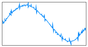
Electrical “noise” is a random, undesired, high-frequency interference of an electrical signal. Noise can originate within a system itself (internal noise) via faults in the switchgear and broader electrical design, and/or leakage current (as described in detail below); or from external sources, like electromagnetic interference from currents in cables, and frequency interference from nearby equipment.
While noise can affect both power and signal circuits, it becomes particularly problematic when it infiltrates information-carrying signal circuits (like those utilized in audio, video, and computing equipment) as they “can be disrupted by as little as 1V.”⁸
“One especially troublesome problem is that of systems featuring several elements in different locations, powered from different branch circuits, but linked by a data cable that carries its own zero reference—a conductor linking the grounding connections in the different locations. Under moderate conditions, the ground loop thus formed can couple noise into the signal path. Under more severe conditions, such as a power system fault or a surge being diverted through the grounding conductors, substantial differences can exist between the ‘ground’ potential of two distant elements of the system; this difference in potential can cause component failures in the circuits.”¹⁰
Using common mode surge suppression may expose sensitive electronic equipment to much higher voltages than they can tolerate.
Leakage Current
Leakage current describes current that is non-functional and unintentional. Leakage current can flow when an inadvertent electrical connection between the ground and a current carrying conductor is created, as in a phase-to-ground SPD application.
If the current is too low to activate safety devices (e.g. breakers and fuses), a touch hazard is created. Leakage current beyond 30mA constitutes a lethal touch safety hazard.⁹
Short-Circuit Failure
When an MOV is exposed to stresses beyond its specifications, it can fail in short-circuit mode. If the applied conditions greatly surpass the device’s energy rating and the current is not restricted, the MOV may be entirely destroyed (often violently).
“…When (MOVs) reach end-of-life, they can approach a short circuit and overheat. In most simplistic terms, an instantaneously overheating MOV can explode. A ‘slowly’ overheating MOV could catch fire in a thermal runaway scenario.”⁴
Manufacturers can integrate a means of disconnection (e.g. fusing) for such circumstances. However, if the disconnection element does not operate properly, or fails altogether, objectionable current will flow on the ground, creating a touch safety hazard (a violation of NEC 250.6a).
Utilizing neutral-to-ground mode surge protection can institute a neutral-to-ground connection if the MOVs fail in short-circuit mode and its means of disconnect fails to operate as designed. The current intended for the neutral would then flow to the ground, creating a touch safety hazard.
This connection also creates an inadvertent bypass of the breaker functionality within the system, a safety hazard in and of itself.
Redundancy
If a proper neutral-ground bond exists at a service entrance or on the secondary side of a building transformer as dictated by the NEC in 250.28, neutral-to-ground suppression circuits provide no additional benefits over phase-to-neutral suppression circuits.
“An additional point to consider is: ‘any hot to ground or neutral to ground transient is converted to hot to neutral transient by the building transformer alleviating the need for protection between any conductors but the hot and neutral.’”¹
Neutral transformer grounding provides a conductive path to the earth, which has sufficient capacity to carry any fault current and low enough impedance to limit voltage rise above ground; it also ensures the proper operation of protective devices in the circuit. These functions help reduce shock hazards to personnel and minimize damage to equipment.⁶
Conclusion
Utilizing common mode suppression can cause unintended performance and safety concerns. Designers and end users should weigh the risks of common mode suppression against its proposed benefits.
Resources
- K. Eilers, M. Wingate, E. Pham, “Application and Safety Issues for Transient Voltage Surge Suppressors,” IEEE Transactions on Industry Applications, Vol. 36, No. 6, November/December 2000.
- National Electrical Code, National Fire Protection Association, Quincy, MA, 2023.
- Lorenzo Mari, “AC Equipment Grounding: Creating a Safe Fault Current Path to Ground,” EE Power – Technical Articles, August 07, 2020.
- TPMOV® construction and operation, Dave Komm-Mersen, 374 Merrimac Street, Newburyport, MA 01950
- Philip F. Keebler, Kermit O. Phipps and Doni Nastasi, “Distinguishing between Surge- and Temporary Overvoltage-Related Failures of Metal Oxide Varistors in End-Use Equipment Designs,” Interference Technology, November 22, 2006.
- Howard Eaton, “5 Questions on Transformer Grounding,” Southwest Electric Co., May 5, 2024.
- Littelfuse Varistors – Basic Properties, Terminology and Theory, Application note, July 1999 AN9767.1
- Rudy Harford, “What to Know About Common Mode Surges and Ground Contamination,” EC&M, Oct. 1, 2004.
- “Equipment protection from leakage current,” EPR Magazine, June 11, 2019.
- “IEEE Recommended Practice for Powering and Grounding Electronic Equipment,” 2005 Emerald Book, IEEE Std 1100™-2005.

