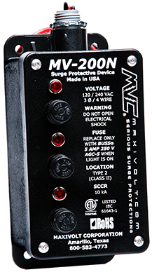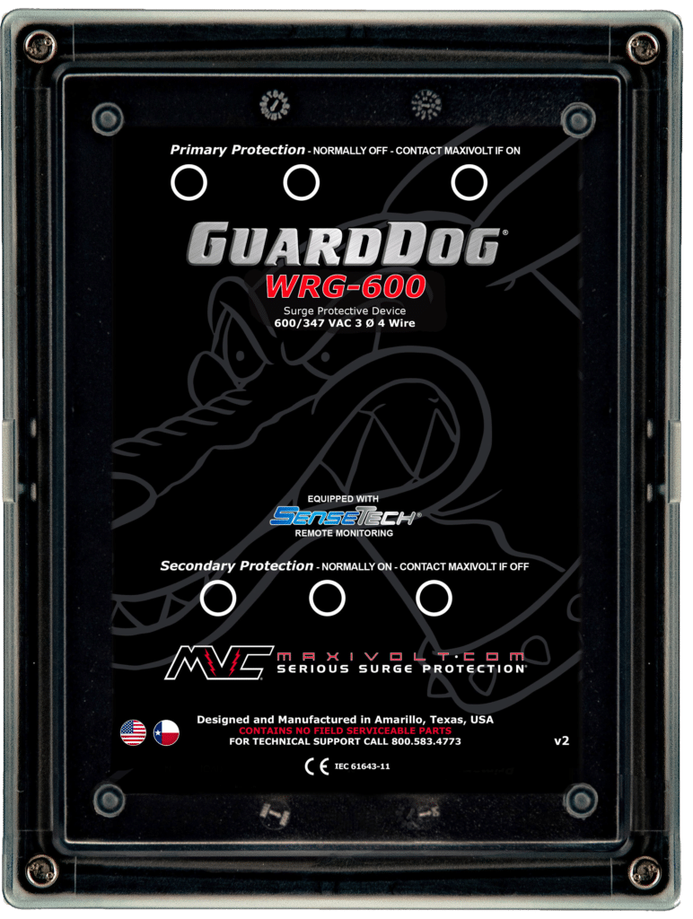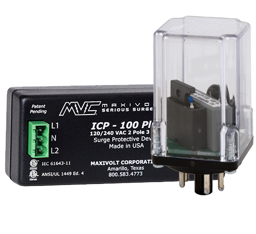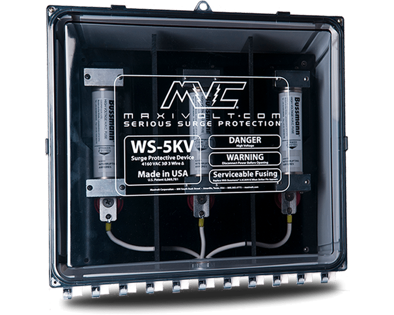
The MV-Series is Maxivolt’s original product line. Modifications through the years have improved the already legendary performance of these devices. The line has been expanded to 17 standard models covering virtually every type of AC power system in the world from 120 VAC to 600 VAC. Every device is hand made in the USA and goes through a rigorous and demanding testing process. MV-Series products feature hybrid circuits consisting of only the highest quality components engineered to provide an industry best clamping threshold for the specific voltage application they are designed for. Serviceable safety fusing and the non-ground dependent design eliminate safety risks associated with competitive devices. The various benefits of MV-Series products provide clients with a quantifiable payback.
THE MV-200N
- Serviceable Safety Fusing
- Hybrid Surge Suppression Circuit
- No Ground Connection
- Durable Catalyst Paint
- Low Clamping Voltage
- Low Surge Current Rating
- 5 Year Warranty
- ETL-EU Listed to IEC 61643-1
APPLICATION
Voltage
120/240 VAC
Configuration
3 Ø / 4 Wire [Hi-Leg]
CHARACTERISTICS
Fusing
Buss 5 Amp 250V AGC-5
Indication
Normally Off Neon Lights
Conductor
14 AWG Stranded
Markings
Silk Screened
Enclosure
NEMA® Type 3R
CERTIFICATIONS
Listing
ETL-EU IEC 61643-11
Environmental
RoHS
DIAGRAM
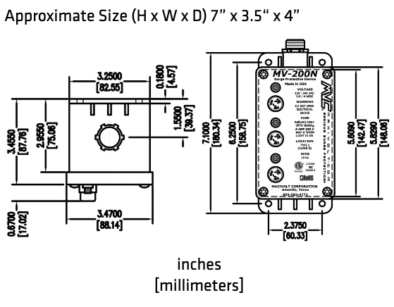
SPECIFICATIONS
Modes of Protection
L-N, L-L
Type (Class)
2 (2)
Nominal Discharge Current
2 kA
Clamp Voltage L-N (L-L) [Hi-Leg]
220 (440)[390]
VPL [Up] L-N (L-L) [Hi-Leg]
500 (960)[780]
SCCR
10 kA
MCOV L-N (L-L) [Hi-Leg]
140 (280)[250]
Operating Temperature
-40° C to 85° C
Operating Humidity
1% to 95%
Filtering
UL 1283
EMI-RFI Noise Attenuation
< 40 db
Capacitance
1 to 1.5 uF / Line
Component Response Time
< 1 ns
Rated Power Dissipation
<1 W / Line
Frequency Range
50 - 400 HZ
Degree of Protection
IP 20
STANDARD INSTALLATION SUMMARY
Install According To Instructions Provided With Device

- Remove 1/2” knockout.
- Mount using mounting feet with proper anchors.
- Connect one black conductor to phase A.
- Connect red conductor to (high leg) phase B.
- Connect other black conductor to phase C.
- Connect white conductor to neutral.
- Install fuses.
Note: Breaker Size 15 amp (if required).
Note: Never add length to provided conductors.
Note: For optimum SPD performance minimize conductor length and avoid sharp bends.
MAXIVOLT
Serious Surge Protection®
WS Series
Made in the USA
We'd love to hear from you
Contact Us
A team of power quality specialist to help you find a solution for your power quality issues. With vast experience and knowledge protecting industries from transient voltage, our team will help you with product selection, placement, and installation are critical to the performance of a surge protection system.
