Solutions to Common VFD Faults
Key Takeaways
- Variable Frequency Drives (VFDs) are highly susceptible to environmental conditions.
- Regular maintenance is key to VFD longevity.
- Maintenance and voltage/current protection are keys to ensuring mean time between failures of the drives.
- If not correctly addressed, these issues lead to downtime, equipment misoperation, or failure of the VFD itself.
Introduction
Variable Frequency Drives (VFDs) are an efficient way to run motors, pumps, or other similar devices, as a means of optimization. However, troublesome faults do arise with VFD use. These faults can crop up due to a number of scenarios, including insufficient maintenance, environmental conditions, as well as power quality issues arising from various sources. When these issues are not proactively addressed, it leads to downtime, equipment misoperation, or failure of the VFD itself.
VFD Fault Modes
VFD faults can land in several categories:
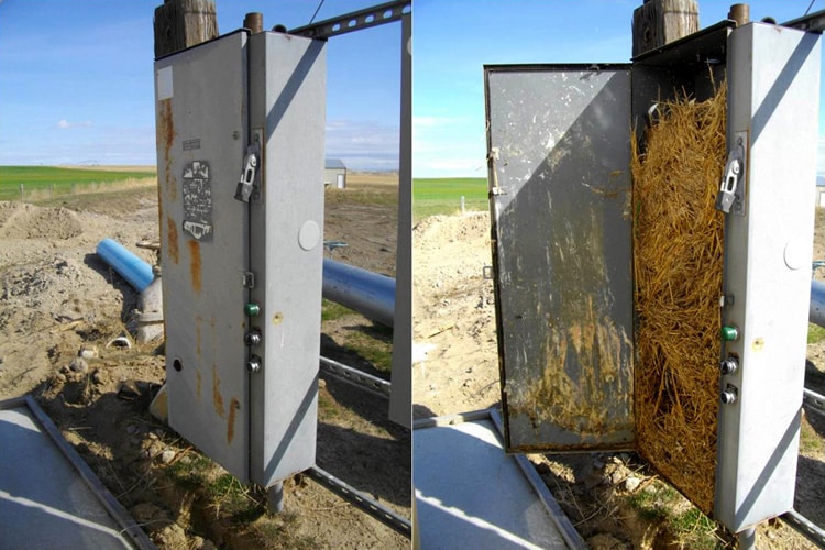
Environmental – Much like computers, VFDs are extremely susceptible to dust, debris, moisture, and excess heat. These environmental factors can significantly reduce the operating life of your VFD.⁴ (See Image 1 for example of debris within a VFD enclosure.)
Component Failure – Whether due to contamination buildup, environmental factors, exposure to power quality issues, or age-related wear and tear, components eventually expend, inducing a fault.
Loose Connections – When connections are not completely secured, drive performance can be erratic, resulting in unpredictable speed fluctuations. Electrical arcing can also occur. Arcing causes catastrophic equipment failure, and poses a major safety issue for employees and technicians.³
Overcurrent – Unexpected high currents send VFDs into overcurrent faults. Frequent sources of overcurrent include short circuits, excessive load, incorrect design or coordination with the load, arc faults and ground faults.⁵
Overvoltage – An overvoltage fault (also known as a high/extreme bus fault) is a common fault caused by an instantaneous spike in voltage and/or the overhauling load originating from the inertia of the connected machine. When this happens, the VFD attempts to protect itself by tripping and shutting off the IGBTs on the inverter side.³

VFD Fault Solutions
Environmental, Component Failure, and Loose Connection-Associated Faults
Appropriate VFD application (the right VFD design for the environment) and a preventative maintenance schedule will address most VFD faults associated with environmental factors, component failure, and loose connections.
When selecting a VFD, consumers need to account for how hot, humid and dirty the installation environment will be. Some drives come completely enclosed, allowing for heat build-up. Others are ventilated, but this allows dirt particles to infiltrate the unit, making a consistent maintenance schedule paramount to ensure proper functionality. Some VDFs even come with a cooling system to combat both these issues, but again, such a setup requires upkeep. Drive selection all depends on the necessities needed to operate the drive in the best operational situation possible. A drive should be properly engineered to handle the torque, ambient temperatures, and system loads in the given application.
Timely, preventative maintenance is also key in fault avoidance. See a potential VFD maintenance checklist below:
- Ensure all connections are tight and visually inspected for loose connections.
- Clear dust/debris and protect drive against moisture.
- Confirm VFD is not overheating (especially in high heat environments); thermal imaging is recommended as high ambient temperatures can mask hot spots by heating the entire object.
Proactively replace worn parts (i.e. cooling fans 1-2 years, capacitors every 3-4 years, etc.)
Refer to NFPA 70B for guidance on maintenance timing.


Overcurrent and Overvoltage Faults
The source of overcurrent and overvoltage faults boils down to one thing: power quality.⁶ Fluctuations in the quality of the electricity supplying VFDs originate from numerous sources – short circuits, utility grid switching, lightning strikes, or (most commonly) start/stop issues within the electrical system.
VFD users may implement numerous methods to solve drive misoperation due to power quality issues, including DC link chokes, smoothing capacitors, AC line reactors, and transient voltage surge suppressors (TVSS).
DC Link Chokes – Connected between the diodes and the DC bus to reduce harmonics from the system, DC link chokes add necessary current impedance without lessening voltage. However, because of their downstream placement, they cannot protect the front end of the drive.1
Smoothing Capacitors – Installed behind a rectifier in parallel with a load, these capacitors reduce AC ripple remaining on the DC rail after rectification. When the rectifier current rises, the capacitor stores the electrical charge; when the rectifier current falls, it releases the stored charge. Though they do not provide total voltage stability, they can provide a smoother AC sine wave for the load being supplied.
AC Line Reactors – Connected on the line side of the drive, AC Line Reactors reduce harmonics by adding impedance (similar to DC Link Chokes). Their disadvantage lies in the fact that they can introduce a voltage drop into the system – a power quality issue in and of itself. This can lead to under-voltage trips in systems with unstable input voltage. The voltage drop may also reduce the DC bus voltage and negatively impact the drive’s output.1
TVSS – TVSS, also called surge protective devices (SPDs), protect against transient voltage events. When properly sized for the voltage tolerances of the system, the device will clamp transient overvoltages before they affect equipment operations. Placement at the input protects the drive from incoming transients while hardening the rest of the system from transients generated by the VFD itself.
Note that DC link chokes, smoothing capacitors, and AC line reactors mitigate current while TVSS addresses voltage. Often a combination of these power quality mitigation devices is required to address VFD faults. A study by the Electric Power Research Institute (EPRI) demonstrates that “when the reactors were coupled with the clamping device (TVSS), the [VFDs] could ride through the transient.”8
“When the reactors were connected to the drive, the peak inrush current associated with the transient increased. Although the clamping device alone was able to reduce the peak inrush current, it was not effective in reducing the peak inrush current when reactors were also connected.”8
See Tables 1 and 2 for study results.
VFDs Cause Power Quality Issues
While VFDs are susceptible to power quality issues, it is noteworthy that they can also act as a source of power quality issues. The switching on and off of VFDs creates a pulse-width modulated (PWM) waveform with high-frequency harmonics. The higher the VFD’s switching rate, the higher the order of harmonics produced.1
Defined as currents or voltages that occur at multiples of the main power frequency, harmonics can cause hosts of problems, most commonly including:
Overheating – Harmonic currents create excess heat in transformers, motors, other equipment, and components of the VFD itself, which leads to premature failure.⁷
Voltage distortion – Harmonic currents distort voltage waveforms, which causes misoperations in sensitive equipment (like computers and control systems).⁷
Resonance – Harmonics cause resonance in the power system, leading to voltage surges and, thus, equipment misoperations and failures.⁷
Chokes, line reactors, and harmonic filters can mitigate harmonics.
Switching within the VFD itself can also cause transient voltages. When switching any component (like breakers and contactors), a transient response is created. The transient will go both up and downstream through the system. Add TVSS to both the input (and in some cases the output) of the VFD to address its inherent transient voltage creation. Installing TVSS on the output of a drive can create other issues so consult with a TVSS application expert before installing.
Conclusion
Ensuring the optimal performance and longevity of VFDs requires a proactive approach that combines proper drive selection, rigorous maintenance, and power quality management. By understanding the common fault modes—whether environmental, component-related, or electrical—operators can implement preventative measures that reduce the risk of downtime and extend the life of their equipment. Integrating power quality mitigation devices (like DC link chokes, smoothing capacitors, AC line reactors, and TVSS) further enhances drive reliability by addressing the root causes of overcurrent and overvoltage faults. With a well-rounded strategy that includes both preventative maintenance and protective measures, VFD misoperations and premature failures can be minimized, leading to improved system efficiency and reduced operational costs.
Resources
- Eaton Corporation (2015, March 1). Low Voltage Drives Harmonic Mitigation Comparison: AC Line Reactors vs. DC Link Chokes. Eaton.com. Retrieved August 20, 2024, from https://www.eaton.com/content/dam/eaton/products/industrialcontrols-drives-automation-sensors/variable-frequency-drives/h-max-variable-frequency-drives/ac-line-reactors-dc-link-chokes-ap040109en.pdf
- (n.d.). Capacitor Smoothing Circuits & Calculations. Electronics-Notes.com. Retrieved August 20, 2024, from https://www.electronics-notes.com/articles/analogue_circuits/power-supply-electronics/capacitor-smoothing-circuits.php
- Mugo, S. (2023, January 10). Motor Starters Part 8: Causes of Variable Frequency Drive Failures. Eepower.com. Retrieved August 20, 2024, from https://eepower.com/technical-articles/motor-starters-part-8-variable-frequency-drive-failures/#
- Kennedy, D. (2021, May 20). Common Causes of VFD Failure. Goemc.com. Retrieved August 20, 2024, from https://goemc.com/2021/05/20/common-causes-of-vfd-failure/
- Yaskawa (2024, August 8). Troubleshooting an oC (Overcurrent) Fault. Yaskawa.com. Retrieved August 20, 2024, from https://solutioncenter.yaskawa.com/selfservice/viewContent.do?externalId=10095&sliceId=1#:~:text=An%20oC%20(Overcurrent)%20fault%20will,too%20small%20for%20the%20motor.
- Penna Electric (n.d.). What’s The Difference Between Overcurrent, Overvoltage & Overload? Pennaelectric.com. Retrieved August 20, 2024, from https://www.pennaelectric.com/overcurrernt-vs-overvoltage-vs-overload/
- Sinwer, R. (2023, March 20). Variable Frequency Drives & Harmonics: Cause, Problems, and Solutions. https://www.linkedin.com/pulse/variable-frequency-drives-harmonics-cause-problems-solutions-sinwer/
- Electric Power Research Institute. (2004). The Performance of a Capacitor-Switching-Transient Clamping Device for Adjustable-Speed Drives. In PQ Brief.


