Modern ATS Components Are Highly Susceptible To Failure Caused By Transient Voltage
Key Takeaways
- Transient voltage is inherent to AC power systems. Modern automatic transfer switches (ATSs) contain sensitive components that are highly susceptible to damage caused by transient voltage.
- Voltage monitoring control boards and control power supplies commonly fail due to damage caused by transient voltage. These failure modes result in ATS inoperability.
- Proper application and installation of suitable surge protective devices is a proven solution to these common failure modes.
- Preventing these failure modes mitigates system downtime, reduces maintenance expenses, and enhances overall system reliability.


Introduction
Individuals and businesses use automatic transfer switches (ATSs) in critical locations requiring both normal and emergency power sources. Reliable operation of the ATS is essential in ensuring uninterrupted power delivery to important electrical and electronic equipment.
Modern ATS utilize sensitive electronic controls to monitor power and initiate switching between power sources. Transient voltage presents a persistent threat to modern ATS components. Properly applying and installing suitable surge protective devices eliminates this threat and significantly enhances ATS reliability.
Transient Voltage
Voltage transients (also known as voltage spikes or surges) are extremely short duration voltage increases. They are created by a variety of culprits. Inductive load switching causes the majority of voltage transients. Weather, especially lightning, is also a significant source of transient voltage.
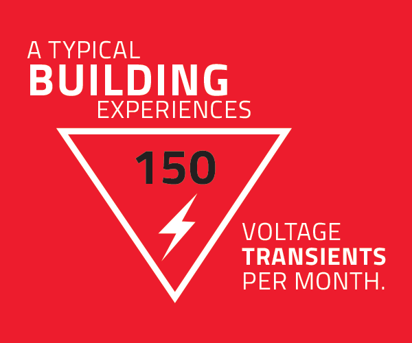
According to The Institute of Electrical and Electronics Engineers (IEEE), voltage transients are inherent to AC power systems. While the frequency and magnitude of these events varies, a typical building experiences an average of 150 voltage transients per month according to The National Electrical Manufacturers Association (NEMA).
The effects of transient voltage can be categorized into three groups:
- Catastrophic Failure – Equipment/component failure caused by a catastrophic voltage transient, commonly attributed to lightning.
- Latent Failure – Equipment/component failure caused by the cumulative effect of exposure to voltage transients, commonly attributed to inductive load switching.
- Integrated Circuit Malfunction – Lockups, malfunctions, and other misoperations attributed to transient voltage exposure.
Common ATS Failure Modes
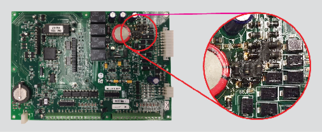
The voltage monitoring control board and control power supply in modern ATSs are highly susceptible to failure caused by transient voltage. These critical parts consist of integrated circuits and other components with transient voltage tolerances as low as two-times nominal voltage. AC power from both the normal and emergency sources inherently contains voltage transients in excess of these components’ tolerances. The cumulative effect of exposure to these transients is component failure which leaves the display panel dark and the ATS inoperable.
Solution
Properly applying and installing suitable surge protective devices (SPDs) is a proven solution to these failure modes. Four key factors should be considered when determining the suitability of an SPD.
- Clamping Voltage – The SPD being applied must have a clamping voltage of less than two-times nominal voltage. If the clamping voltage exceeds two-times nominal voltage, component degradation will occur, ultimately resulting in latent failure.
- Response Time – The SPD being applied must have a component response time value of less than one nanosecond. If the component response time exceeds one nanosecond, components can be exposed to transient voltage before the SPD is able to react.
- Monitoring Capabilities – Due to the sacrificial nature of SPDs, it is critical to monitor their status. Failing to do so can result in a scenario where the ATS is left vulnerable due to an expended SPD. Applying an SPD with both a primary and a secondary level of surge suppression further reduces the opportunity for windows of exposure.
- Safety Features – Applying a properly fused SPD without line to ground (L-G) or neutral to ground (N-G) modes of protection eliminates unnecessary safety risks. A non-fused or improperly fused device can ignite or explode in the event of a metal oxide varistor (MOV) failing in a dead short. Integral, coordinated, current-rated fusing provides the most reliable and predictable means of disconnect in the event of MOV failure. These modes also create a path for ground faults and ground lightning strikes to be coupled back into equipment causing damage.
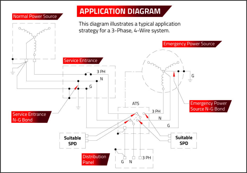
SPD Application and Installation
Properly applying and installing suitable SPDs is critical to performance. An SPD must be applied on both the normal and emergency source terminals to protect components from both sources. Connecting the device to a means of disconnect allows the SPDs to be serviced without interrupting power. The lead conductors should be appropriately sized, free of sharp bends, and cut as short as possible. This ensures proper operation of the SPD by making it the path of least resistance in the system.
Benefits
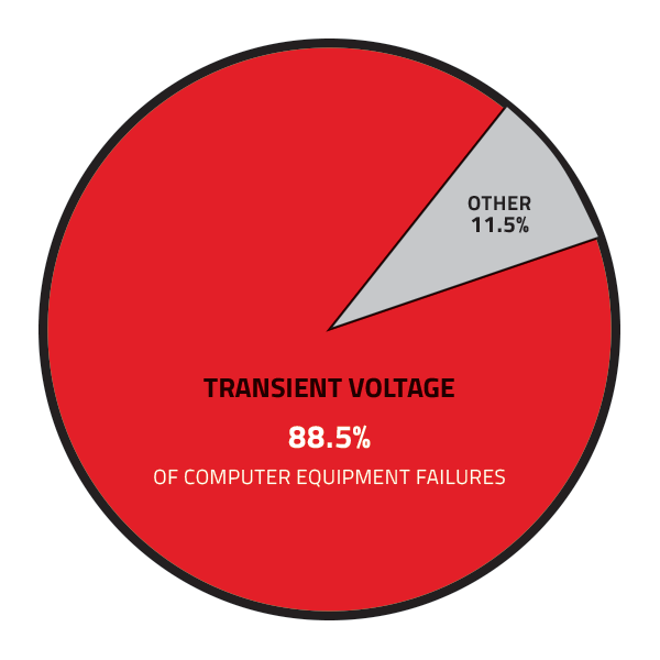
Protecting an ATS with suitable SPDs greatly reduces the opportunity for ATS failure and malfunction. A benchmark study conducted by IBM, Monitoring of Computer Installations for Power Line Disturbance, monitored AC power at 200 locations in 25 US cities over a two-year timespan. The results of the study reported that voltage transients directly caused 88.5% of computer equipment failures. Preventing these failures mitigates system downtime, reduces maintenance expenses, and enhances overall system reliability.
Real World Results
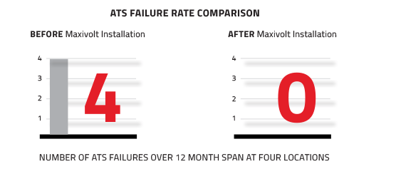
One electric utility company owns and maintains more than 1,200 substations across 10 states. A survey of a small sampling of ATSs in these substations determined a trend of voltage monitoring control board and power supply failures. Four substations had experienced such failures in the prior 12 months. At these locations, the utility company retrofitted the ATSs with Maxivolt SPDs. Initially, ICP-Series devices were installed on both normal and emergency inputs. Within six months of the retrofit, the devices had expended multiple times, effectively protecting all ATS components in each instance. Due to the frequency of expenditures, the utility company chose to replace the ICPs with more robust, WRG-Series devices. Six months after installing WRGs, they reported zero ATS component failures and zero WRG expenditures. Based on failure rates before and after installing Maxvolt SPDs, it is reasonable to conclude multiple ATS failures were successfully averted.
Transient voltage inside ATS systems isn’t incidental—it’s built into how they operate. If switching events are stressing your components, protection needs to be engineered, not assumed.
Talk with Maxivolt about a solution designed for ATS environments—one that addresses internal transients, coordinates with your system, and protects what standard approaches miss.
References
- Monitoring of Computer Installations for Power Line Disturbance, G.W. Allen and D. Segall of IBM System Development Division
- IEEE C62.72 Guide for the Application of Surge Protective Devices
- NEMA The Need for Surge Protective Devices